 English
 中文简体
中文简体 عربى
عربى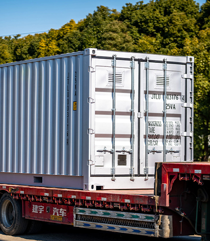
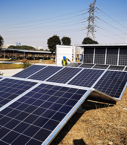
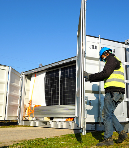
Prefabricated photovoltaic (PV) cabins house inverters, batteries, transformers and control gear; their structural integrity is critical where wind or seismic hazards are significant. Reinforcement strategies must address overturning, uplift, lateral drift, dynamic amplification and equipment protection. This article gives practical, engineering-focused measures you can apply: foundation options, superstructure stiffening, connections and anchorage details, dynamic mitigation (dampers, base isolation), material and corrosion considerations, and on-site validation.
Content
- 1 Foundations and anchorage: the first line of defense
- 2 Superstructure stiffening and lateral load paths
- 3 Wind-specific reinforcements: uplift, suction and cladding
- 4 Seismic-specific measures: ductility and energy dissipation
- 5 Equipment anchorage, internal bracing and service resilience
- 6 Materials, corrosion protection and lifecycle considerations
- 7 Inspection, testing and validation
- 8 Comparison table: reinforcement strategies and typical use-cases
- 9 Design checklist for engineers and project managers
- 10 Conclusion: integrated approach reduces risk
Foundations and anchorage: the first line of defense
Foundations transmit wind uplift, overturning moments and seismic shear to the ground. Select foundation types by soil, frost depth, and service loads: spread footings, combined footings, pile foundations, or concrete pads with cast-in anchors. For high wind zones, size anchor embedment and bolt diameters to resist predicted uplift and pull-out per design codes (for example ASCE 7 or local equivalents). For seismic zones, design foundations for combined vertical and horizontal loads, account for overturning, and provide adequate base shear capacity with sufficient embedment length and development length for anchor bolts.
Bolt pattern and anchor types
Use multiple anchor bolts in symmetric patterns to reduce eccentricity and bending on anchors. Chemical anchors or cast-in headed studs reduce pull-out risk compared with simple expansion anchors, especially under cyclic loading. Provide anchor plates or gusseted baseplates to spread load into the concrete and prevent localized breakout.

Foundations for variable soils
In poor soils consider driven or bored piles, micropiles, or enlarged footings. For seismic liquefaction-prone sites, choose deep foundations or ground improvement; include settlement and uplift checks for cyclic loads. Pile-head caps should be tied with reinforcement cages using ductile detailing to resist seismic demands.
Superstructure stiffening and lateral load paths
Provide continuous, clearly defined lateral load paths from roof and walls to foundation. Stiffening measures include diagonal bracing, shear walls, rigid moment frames and floor/roof diaphragms. Steel C-frames or box-section frames integrated into the cabin shell increase stiffness and reduce drift under seismic excitations. Ensure connections (welds, bolted gussets) are designed for both strength and ductility to avoid brittle failure modes.
Diaphragms and shear panels
Design roof and floor panels as diaphragms to collect lateral loads from walls and distribute them to shear walls or braced frames. Use continuous sheathing fixed with appropriate fasteners and provide collector elements (drag straps) at diaphragm edges to transfer forces to vertical elements.
Wind-specific reinforcements: uplift, suction and cladding
Wind loading produces both positive pressure and negative suction, especially on corners and roof edges. Reinforce roof-to-wall connections with continuous clips or heavy-gauge angle brackets sized for uplift. Increase roof diaphragm fasteners at perimeter zones, and specify roof sheathing with adequate pull-through resistance. Design overhangs and louvers to reduce local suction and provide aerodynamic detailing where possible.
Cladding and sealing strategy
Use through-fastened cladding to structural members and add secondary retention (screws with backing plates or clips) to prevent wind-driven detachments. Provide flexible flashings and pressure-relief pathways to avoid internal pressurization that increases uplift on panels.
Seismic-specific measures: ductility and energy dissipation
Seismic design emphasizes ductility and energy absorption. Use ductile steel details, avoid brittle welds at high-stress regions, and prefer bolted connections with slotted holes for controlled deformation. Introduce sacrificial or replaceable components (fuse plates, shear links) in the load path to protect primary members.
Base isolation and damping
Where site seismicity and budget permit, base isolation systems (elastomeric bearings or sliding bearings) decouple the cabin from ground motion, reducing relative displacement and acceleration transmitted to equipment. Alternatively, add viscous or friction dampers within braced frames to dissipate energy and limit peak demands on anchors and equipment mounts.
Equipment anchorage, internal bracing and service resilience
Secure in-cabin equipment (batteries, inverters, racks) to the structure using seismic-rated anchors and restraining frames. Provide continuous rack-to-floor connections, tethering for tall components, and internal partition bracing to prevent racking. Route heavy cable trays along structural members and secure flexible loops for vibration isolation. Include ventilation and HVAC mounts that limit resonant amplification and avoid transferring excessive loads to the cabin shell.
Mounting of battery systems
Battery racks require robust anchorage and ventilation pathways. Use seismic-rated rack systems with bolted cross-bracing and shear panels. Provide secondary containment for electrolyte leaks and design fast-release restraints for maintenance that do not compromise seismic retention.
Materials, corrosion protection and lifecycle considerations
Choose materials and coatings that maintain strength and toughness under cyclic loading and in the local environment. Hot-dip galvanizing, stainless steel fasteners, epoxy primers and polyurethane topcoats extend life in coastal or corrosive sites. Pay attention to thermal effects: differential expansion between steel frames and concrete pads can affect anchor loads.
Inspection, testing and validation
Validate designs with peer-reviewed calculations and, where appropriate, dynamic analysis (modal, response spectrum or time-history). Perform on-site inspection of anchor torque, weld quality, and grout fills. Conduct pull-out tests on representative anchors, and perform non-destructive testing (NDT) on critical welds. After installation, functional tests and shake-table tests on prototype cabins provide high-confidence validation for extreme sites.
Comparison table: reinforcement strategies and typical use-cases
| Strategy | Primary benefit | When to use | Notes |
| Deep pile foundations | Resists uplift, settlement, liquefaction | Weak soils, high seismicity | Higher cost, longer install |
| Base isolation | Reduces seismic forces transmitted | High seismic zones, critical equipment | Maintenance required for bearings |
| Diagonal bracing / shear walls | Limits lateral drift, provides ductility | Both wind and seismic applications | Must be tied to diaphragms |
| Dampers / energy dissipation | Reduces peak response, protects anchors | Retrofit or where isolation not feasible | Adds cost, but reduces member sizing |
Design checklist for engineers and project managers
- Confirm site hazard data: design wind speeds, seismic zone, soil report and liquefaction potential.
- Select foundation and anchor system sized for combined wind uplift and seismic base shear.
- Provide clear lateral load paths: diaphragms, collectors, bracing and shear walls.
- Design connections for ductility; prefer replaceable sacrificial elements where useful.
- Specify corrosion protection and maintenance access for bearings, anchors and dampers.
- Plan inspection, load testing and, if needed, prototype dynamic testing before series production.
Conclusion: integrated approach reduces risk
Effective reinforcement of prefabricated PV cabins combines proper foundation selection, robust anchor design, defined lateral load paths, ductile connections, and dynamic mitigation where needed. Consider lifecycle, corrosion and maintenance when specifying solutions. Use site-specific hazard data and validated analysis methods to justify reinforcement levels; where uncertainty exists, conservative detailing and prototype testing provide valuable risk reduction.
