 English
 中文简体
中文简体 عربى
عربى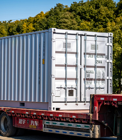
A battery energy storage system (ESS) container — commonly called a BESS container or containerized energy storage system — is a factory-integrated, self-contained energy storage unit built within a standard or custom steel enclosure that houses battery modules, a battery management system (BMS), power conversion equipment, thermal management systems, fire suppression, and safety controls in a single transportable package. It is the dominant deployment format for grid-scale and commercial energy storage worldwide because it combines factory quality control, rapid field deployment, scalability through parallel connection of multiple units, and standardized logistics using ISO shipping container dimensions. For utility-scale projects, commercial and industrial (C&I) peak shaving, renewable energy integration, and off-grid power applications, the containerized ESS is the most practical and cost-effective approach to deploying energy storage at any scale from 100 kWh to hundreds of MWh.

Content
- 1 What a Battery ESS Container Actually Contains
- 2 Battery Chemistry: Why LFP Dominates ESS Containers
- 3 Thermal Management: The Critical System That Determines Battery Life
- 4 Fire Safety and Suppression in Battery ESS Containers
- 5 Container Sizing, Capacity, and System Configuration
- 6 Applications: Where Battery ESS Containers Are Deployed
- 7 Standards and Certifications for Battery ESS Containers
- 8 Evaluating and Selecting a Battery ESS Container: Key Criteria
What a Battery ESS Container Actually Contains
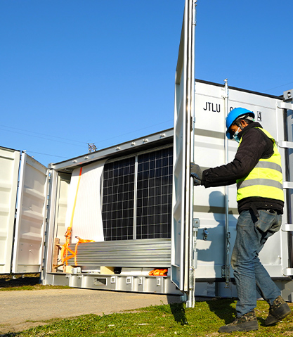
A containerized battery ESS is not simply batteries in a box. It is a fully integrated power system in which every subsystem is engineered to work together within the space and weight constraints of the enclosure. Understanding the complete system architecture is essential for evaluating specifications, comparing suppliers, and ensuring the system will perform as designed over its intended service life.
Battery Modules and Racks
The battery cells — almost universally lithium iron phosphate (LFP) chemistry in current utility and C&I deployments — are grouped into modules (typically 10–50 kWh per module) and then into racks (typically 100–300 kWh per rack). Multiple racks are installed in the container in rows, with cabling, busbars, and cooling infrastructure connecting them. A standard 20-foot equivalent unit (20ft) ESS container typically accommodates 8–12 racks, delivering system capacity in the range of 500–1,500 kWh depending on the energy density of the cell technology and rack design. A 40-foot container format (40ft) can deliver 1,500–4,000 kWh or more as cell energy density continues to improve with each product generation.
The trend from 2022 onward has been toward larger-format LFP cells — particularly the 280 Ah prismatic cell (now approaching 314 Ah and 320 Ah in leading manufacturers' offerings) and the blade cell format — which deliver higher energy density per rack and lower internal resistance, improving both round-trip efficiency and thermal performance. Higher-capacity cells also reduce the total number of cells in a system, reducing the number of potential failure points and simplifying the BMS monitoring task.
Battery Management System (BMS)
The BMS is the intelligence layer of the battery system, monitoring and controlling the state of every cell or module group to ensure safe and optimal operation. A multi-level BMS architecture is standard in quality ESS containers:
- Cell-level or module-level BMS (slave BMS): Monitors individual cell voltage, temperature, and state of charge (SoC) within each module. Triggers cell-level protection (disconnection) if parameters exceed safe limits.
- Rack-level BMS: Aggregates data from module-level BMS units, controls the rack contactor, manages cell balancing, and communicates rack state to the master BMS.
- System master BMS (MBMS): Coordinates all racks within the container, communicates with the energy management system (EMS) and power conversion system (PCS), calculates system-level state of charge and state of health (SoH), and executes protection algorithms at the container level.
Key BMS performance parameters include cell balancing accuracy (typically ±5–20 mV per cell), SoC estimation accuracy (±2–3% in quality systems), communication protocols (CAN bus, RS485, Modbus, or Ethernet), and response time to fault conditions (typically milliseconds for protection triggers).
Power Conversion System (PCS)
The PCS converts the DC power stored in the batteries to AC power for grid or load connection (and vice versa during charging). In an all-in-one containerized ESS, the PCS is integrated within the container. In modular designs, the PCS may be in a separate container or outdoor cabinet. PCS performance specifications that determine system-level performance include:
- Rated power (kW / MW): The continuous AC output power capacity. For most containerized ESS, power rating is matched to energy capacity for a 0.5C to 1C charge/discharge rate — meaning a 1,000 kWh container has a 500–1,000 kW PCS.
- Round-trip efficiency: The ratio of AC energy output to AC energy input over a complete charge-discharge cycle. State-of-the-art PCS units achieve 97–98.5% DC-AC conversion efficiency, contributing to overall system round-trip efficiency (including battery losses) of 88–93% for LFP-based systems.
- Response time: The time from a control signal to full rated power output. Modern PCS units respond in less than 100 milliseconds — critical for frequency regulation and fast demand response applications.
- Grid-forming vs. grid-following capability: Grid-following PCS units synchronize to the existing grid voltage and frequency. Grid-forming PCS units can establish their own voltage and frequency reference, enabling black-start capability and operation in islanded microgrids without a grid reference — increasingly important for resilience and remote off-grid applications.
Energy Management System (EMS)
The EMS is the top-level control system that manages the ESS container (or multiple containers in a larger system) in the context of the broader energy environment — grid tariffs, renewable generation forecasts, load demand, and operator-defined dispatch strategies. The EMS communicates with the MBMS and PCS through standardized protocols (Modbus TCP, DNP3, IEC 61850, or MQTT/REST API for cloud-connected systems) and executes scheduling algorithms that optimize battery dispatch for the target application — whether peak shaving, frequency regulation, arbitrage, or backup power. For large utility-scale projects, the EMS is often a separate hardware and software platform provided by the project developer or utility, interfacing with the BESS container's BMS and PCS through published communication protocols.
Battery Chemistry: Why LFP Dominates ESS Containers
The chemistry choice in a battery ESS container has fundamental implications for safety, cycle life, temperature performance, and total cost of ownership over the project lifetime. While multiple lithium-ion chemistries have been deployed in energy storage applications, lithium iron phosphate (LFP) has become the overwhelmingly dominant chemistry for containerized ESS as of 2023–2025, displacing nickel manganese cobalt (NMC) and nickel cobalt aluminum (NCA) chemistries that were common in earlier ESS deployments.
| Chemistry | Nominal Voltage | Cycle Life (to 80% SoH) | Thermal Runaway Risk | Energy Density | Relative Cell Cost | ESS Suitability |
|---|---|---|---|---|---|---|
| LFP (LiFePO₄) | 3.2 V | 3,000–6,000+ | Very Low | 120–160 Wh/kg (cell) | Low | Excellent |
| NMC (LiNiMnCoO₂) | 3.6–3.7 V | 1,000–3,000 | Moderate–High | 150–220 Wh/kg (cell) | Higher | Declining in ESS |
| NCA (LiNiCoAlO₂) | 3.6 V | 500–2,000 | High | 200–260 Wh/kg (cell) | High | Rarely used in ESS |
| LTO (Li₄Ti₅O₁₂) | 2.3 V | 10,000–20,000+ | Very Low | 50–80 Wh/kg (cell) | Very High | Niche high-cycle use |
LFP's dominance in ESS containers is driven by three converging factors: its inherently stable olivine crystal structure makes thermal runaway extremely difficult to trigger even under severe abuse conditions (overcharge, penetration, external heat) — the primary fire safety concern for large co-located battery installations; its cycle life of 4,000–6,000 full cycles to 80% capacity retention aligns with the 10–20 year design life of commercial ESS projects; and the dramatic cost reduction in LFP cell manufacturing, with prismatic LFP cells reaching below $80/kWh at spot prices in 2024, making LFP-based ESS containers the most cost-competitive energy storage option for most stationary applications.
Thermal Management: The Critical System That Determines Battery Life
Thermal management is arguably the most consequential engineering subsystem in a battery ESS container. Battery cell degradation rate approximately doubles for every 10°C increase in average operating temperature above the optimal range (typically 20–35°C for LFP). A system operating at 45°C instead of 25°C will reach end-of-life in approximately half the calendar time — a direct impact on project economics. Simultaneously, operating at temperatures below 0°C significantly reduces available capacity and increases internal resistance, limiting power output. The thermal management system must maintain all cells within the target temperature window across ambient conditions that may range from −40°C (Arctic deployments) to +50°C (Middle East and desert environments).
Air Cooling vs. Liquid Cooling
Two primary thermal management approaches are used in containerized ESS:
- Air cooling (HVAC-based): A dedicated air conditioning system maintains the interior of the container within the target temperature band. Air is circulated by fans across the battery racks. Air cooling is mechanically simpler, lower in cost, and easier to maintain than liquid cooling systems. However, it provides less uniform temperature distribution across cells within a rack (particularly for large-format prismatic cells), and its thermal capacity limits the maximum continuous C-rate at which the system can operate without triggering thermal protection. Air-cooled containerized ESS are standard for 0.25C to 0.5C continuous discharge rates and are the most common configuration for energy-focused (long-duration) applications.
- Liquid cooling (direct or indirect): Cooling plates or channels with circulating liquid coolant (typically water-glycol mixture) are integrated into each battery rack, providing direct heat extraction from the cell surfaces. Liquid cooling achieves significantly better temperature uniformity (cell-to-cell temperature variation typically less than 3°C vs. 5–10°C in air-cooled systems), higher heat removal capacity enabling 1C or higher continuous discharge rates, and faster response to transient thermal loads. The tradeoff is higher system complexity, additional leak risk, and higher initial capital cost. Liquid-cooled containerized ESS are preferred for power-focused applications (frequency regulation, fast ramping) and for deployments in extreme climates where the higher thermal capacity provides better protection against ambient temperature excursions.
Cold Climate Operation and Battery Preheating
In cold climates, LFP batteries must be preheated to above 0°C before charging and above −10°C before discharging at rated power to prevent lithium plating (during low-temperature charging) and excessive internal resistance (limiting power output). Quality ESS containers include electric resistance heating elements or heat pump systems within the thermal management circuit to bring the battery temperature to operating range before dispatch is enabled. The BMS should enforce a hard prohibition on charging at cell temperatures below 0°C regardless of external command — a critical safety protection that must be verified during factory acceptance testing.
Fire Safety and Suppression in Battery ESS Containers
Fire safety is the most critical risk management aspect of battery ESS container deployment. While LFP chemistry has substantially lower thermal runaway propensity than NMC or NCA, thermal runaway in large battery systems remains a serious risk — particularly in second-life battery systems, systems with compromised cells, or systems that experience repeated deep cycling beyond their design parameters. Multiple high-profile BESS fires (including incidents in South Korea, Australia, and the United States) have driven significant evolution in fire safety standards and suppression system design.
Thermal Runaway Detection and Early Warning
The most effective fire safety strategy is early detection of thermal runaway before it propagates from an individual cell to adjacent cells, modules, or racks. Detection systems in quality ESS containers include:
- Cell voltage and temperature monitoring: Continuous BMS monitoring detects abnormal voltage drop or temperature rise indicative of early-stage thermal runaway. Response time is critical — the BMS must isolate the affected module within seconds of detection.
- Gas detection sensors: Lithium-ion cells in early-stage thermal runaway vent flammable gases (primarily hydrogen, carbon monoxide, and volatile organic compounds) before significant temperature rise is detectable. Electrochemical or photoionization gas sensors within the battery compartment can provide 30–300 seconds of advance warning before flame or significant heat is detectable — valuable time for system shutdown and suppression activation.
- Smoke and optical flame detection: Conventional smoke detectors and infrared flame sensors provide redundant detection layers. Aspirating smoke detection (ASD) systems that actively sample air from within battery enclosures provide faster response than passive point detectors.
Suppression System Options
Several suppression approaches are used in containerized ESS, each with distinct advantages and limitations for lithium-ion fire scenarios:
- Heptafluoropropane (HFP / FM-200) or FK-5-1-12 (Novec 1230) clean agent: The most common approach in containerized ESS for initial suppression. These agents suppress combustion by chemical inhibition and oxygen displacement, discharged from pressurized cylinders in a total flooding system. Effective for suppressing fire in the container atmosphere, but do not cool the battery cells themselves — if thermal runaway continues within individual cells, the suppression agent provides limited benefit once exhausted. These systems are designed to control the immediate fire risk while the system is shut down, not to extinguish a fully developed cell thermal runaway event.
- Water mist systems: Fine water mist provides both suppression (oxygen displacement and chemical inhibition from steam) and cooling — addressing the limitation of clean agent systems in suppressing thermal runaway propagation. Water mist systems require a water supply connection or onboard tank, adding weight and infrastructure complexity, but provide significantly better thermal management of the fire environment. Some advanced designs integrate water mist directly into the battery rack structure for cell-level cooling during thermal runaway events.
- Direct liquid immersion (emerging): A small number of advanced ESS designs submerge battery cells directly in dielectric cooling fluid. In a thermal runaway event, the fluid provides continuous heat absorption that can prevent propagation to adjacent cells — addressing the fundamental limitation of gaseous suppression systems. This approach is at early commercial deployment stage as of 2025.
Deflagration Venting and Container Structure
A severe thermal runaway event involving multiple cells can produce sufficient flammable gas to create an explosive atmosphere within the container. If ignited, this can result in a deflagration (rapid combustion) that generates overpressure capable of damaging the container structure and creating projectile hazards. Quality ESS containers include pressure relief panels or explosion venting — calibrated structural weak points designed to open and relieve overpressure before it reaches structurally damaging levels, directing the venting to a safe direction away from personnel or adjacent equipment. The sizing and positioning of vent panels is a critical fire safety engineering calculation verified against relevant standards (NFPA 68, EN 14994).
Container Sizing, Capacity, and System Configuration
Battery ESS containers are available in a range of standard sizes, with energy and power capacity determined by the container dimensions, rack configuration, and cell technology. Understanding the sizing landscape helps buyers match available products to project requirements.
| Container Format | Typical Energy Capacity | Typical Power Rating | Approximate Weight | Primary Application |
|---|---|---|---|---|
| 10 ft / Small enclosure | 100–300 kWh | 50–200 kW | 3,000–6,000 kg | C&I, microgrids, distributed storage |
| 20 ft ISO | 500–1,500 kWh | 250–1,000 kW | 15,000–26,000 kg | C&I, utility front-of-meter, microgrids |
| 40 ft ISO (standard) | 1,500–4,000 kWh | 750–2,000 kW | 25,000–50,000 kg | Utility-scale, renewable integration |
| 40 ft HQ / Custom large | 3,000–6,000 kWh | 1,500–3,000 kW | 40,000–60,000 kg | Utility-scale, grid services, LDES |
Scaling to Large Projects: Multi-Container Arrays
Utility-scale energy storage projects in the range of 10–1,000 MWh are built by deploying multiple ESS containers in parallel arrays connected through medium-voltage (MV) or high-voltage (HV) collector systems. Each container operates as an independent DC/AC system, but the EMS coordinates dispatch across all containers to deliver the combined project power and energy to the grid connection point. A 100 MWh project using 4 MWh containers would require approximately 25 containers with associated civil infrastructure (foundations, access roads, fencing, MV switchgear, and SCADA communications).
The spacing and layout of containers in utility arrays is governed by fire safety separation requirements — typically a minimum of 3 meters between containers per NFPA 855 guidance for battery systems, and greater separation may be required by local authorities having jurisdiction (AHJ) or insurance underwriters. This separation requirement significantly affects project land footprint and civil cost, and is one driver behind the trend toward higher-energy-density containers that reduce the total number of units and therefore total land area.
Applications: Where Battery ESS Containers Are Deployed
The containerized ESS format is deployed across a wide range of applications, each with distinct technical requirements for power rating, energy capacity, response time, and cycle frequency. Understanding application-specific requirements is essential for correct system sizing and specification.
Utility-Scale Grid Services
Grid-scale BESS containers provide frequency regulation, voltage support, spinning reserve, and energy arbitrage services to electricity transmission and distribution operators. Frequency regulation requires the fastest response — full power in under 100 milliseconds — and typically operates at moderate depth of discharge with high cycle frequency (1–3 full cycles per day). Energy arbitrage (charging during low-price periods, discharging during high-price periods) requires larger energy capacity and fewer daily cycles. The largest utility-scale BESS projects worldwide now exceed 1,000 MWh (e.g., the Moss Landing Energy Storage Facility in California and multiple projects in Australia's National Electricity Market).
Renewable Energy Integration and Firming
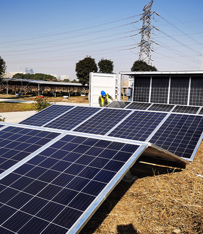
Co-located battery storage paired with solar PV or wind generation allows the combined plant to provide firm, dispatchable power — delivering contracted power output even when solar irradiance or wind speed is temporarily insufficient. This "solar + storage" or "wind + storage" configuration requires an ESS sized to firm generation over the required dispatch window — typically 2–6 hours of rated power for day-ahead commercial contracts. Storage at the point of renewable generation also reduces curtailment (renewable energy that would otherwise be wasted because the grid cannot absorb it at the moment of generation), improving the capacity factor and revenue of the renewable asset.
Commercial and Industrial Peak Shaving and Demand Response
C&I customers with high peak demand charges — where the electricity bill includes a charge based on the highest 15-minute or 30-minute demand in a billing period — can significantly reduce costs by deploying an ESS container to cap peak demand. The ESS charges during low-demand periods and discharges to limit the peak draw from the grid. A 500 kWh / 500 kW ESS container can typically reduce peak demand by 300–500 kW for 1–2 hours, reducing demand charges by $5,000–$20,000 per month for large industrial facilities with demand charges of $15–40/kW/month. The economics of C&I peak shaving are among the most favorable for containerized ESS because the financial return is immediate and predictable based on measurable tariff structures.
Off-Grid and Microgrid Power
Remote communities, mining operations, telecommunications sites, and island power systems use containerized ESS as the storage backbone of hybrid renewable-diesel microgrids. The ESS stores excess solar or wind generation and reduces — or in optimally designed systems, eliminates — diesel generator runtime. In mining applications, a typical hybrid system replacing a diesel generator fleet with solar PV and ESS can reduce fuel consumption by 60–80%, representing multi-million dollar annual savings at remote sites with high fuel logistics costs.
Backup Power and Resilience
Data centers, hospitals, water treatment facilities, and critical infrastructure operators use containerized ESS as a higher-performance alternative to traditional diesel generator backup — with the ESS providing instantaneous, seamless transfer (no generator start delay) and the ability to sustain loads for hours on battery, with diesel generators as a secondary backup for extended outages. This "battery-first" resilience architecture is increasingly standard in new data center construction, where the ESS also provides UPS (uninterruptible power supply) functionality that eliminates the traditional double-conversion UPS systems previously required.
Standards and Certifications for Battery ESS Containers
Regulatory compliance and standards certification are critical requirements for ESS container procurement — both for permitting by local authorities and for acceptance by grid operators and insurance underwriters. The key standards governing containerized battery ESS include:
| Standard | Issuing Body | Scope | Region |
|---|---|---|---|
| UL 9540 | UL (Underwriters Laboratories) | System-level safety standard for energy storage systems | USA (required by many AHJs) |
| UL 9540A | UL | Test method for evaluating thermal runaway propagation in BESS | USA (fire safety planning) |
| NFPA 855 | NFPA | Installation standard for stationary energy storage systems (siting, separation, suppression) | USA |
| IEC 62619 | IEC | Safety requirements for secondary lithium cells and batteries for stationary applications | International / EU |
| IEC 62477-1 | IEC | Safety requirements for power electronic converter systems (PCS) | International / EU |
| IEC 61850 | IEC | Communication networks and systems for power utility automation (grid integration) | International |
| CE Marking (LVD / EMC / Machinery) | EU | Conformity with EU electrical safety, EMC, and machinery directives | European Union |
| GB/T 36276 | SAC (China) | Safety requirements for lithium-ion batteries for stationary energy storage | China |
For projects in the United States, UL 9540 system certification combined with UL 9540A thermal propagation test data is effectively required by most fire authorities and increasingly specified by insurers. UL 9540A testing subjects a single battery module to thermal runaway initiation and documents whether and how the event propagates to adjacent modules and to the system level — providing the data needed to design appropriate suppression systems and siting separation distances. Many major BESS suppliers publish UL 9540A test reports for their current-generation products, and requesting this documentation should be a standard part of any supplier qualification process.
Evaluating and Selecting a Battery ESS Container: Key Criteria
Selecting a battery ESS container involves comparing systems across technical, commercial, and lifecycle dimensions that go beyond the headline capacity and power specifications. The following framework covers the most commercially significant selection criteria.
Round-Trip Efficiency and Auxiliary Power Consumption
System round-trip efficiency (RTE) — the ratio of AC energy out to AC energy in — determines the ongoing energy cost of operation. A system with 88% RTE loses 12% of every kWh cycled through it; a system with 92% RTE loses only 8%. For a 10 MWh system cycling once per day, the annual energy loss difference between 88% and 92% RTE is approximately 146 MWh/year — at $50/MWh, this represents over $7,000 per year in additional energy cost for the lower-efficiency system. Over a 15-year project life, the cumulative difference is substantial. RTE should be measured at the system level (AC-to-AC, including thermal management and auxiliary power) at the specified operating temperature and C-rate — not claimed at the cell level or at unrealistic test conditions.
Cycle Life and Calendar Life Warranty
The battery warranty defines the supplier's commitment to capacity retention over the project life. Standard industry warranty terms guarantee a minimum retained capacity — typically 70–80% of rated nameplate capacity — at the end of the warranty period (commonly 10 years), subject to the system being operated within defined parameters (maximum temperature, DoD limit, C-rate limit). Key warranty terms to scrutinize include:
- Throughput guarantee: Total energy throughput (in MWh) covered by the warranty, which determines the number of cycles available within warranty. A 10 MWh system warranted for 40,000 MWh throughput can cycle approximately 4,000 full cycles — verify this matches the expected application cycle frequency.
- Capacity replacement vs. performance compensation: Whether the supplier will replace battery modules that fail to meet the warranted capacity, or compensate financially for shortfall. Module replacement is operationally more complex but ensures the system maintains its designed capacity; financial compensation may not fully offset the project revenue impact of reduced storage capacity.
- Operating condition limits: Warranty conditions typically specify maximum operating temperature, minimum/maximum state of charge limits, and maximum C-rate. Operating outside these limits voids the warranty — verify that the proposed operating profile is within the warranted envelope.
Factory Acceptance Testing (FAT) and Commissioning
Factory acceptance testing — performed at the supplier's manufacturing facility before shipment — is the buyer's most important quality assurance opportunity. A comprehensive FAT for an ESS container should include:
- Full charge-discharge cycle at rated power to verify energy capacity against nameplate specification
- Round-trip efficiency measurement at specified test conditions
- BMS protection function tests: overvoltage, undervoltage, overcurrent, and overtemperature protection response
- Thermal management system performance verification at simulated load
- Fire detection and suppression system function test (simulated alarm)
- Communications interface verification (EMS/SCADA integration test)
- Review of as-built documentation: single-line diagrams, BMS configuration parameters, cell serial number tracking, and test records
Total Cost of Ownership Calculation
The purchase price of a battery ESS container — typically quoted in $/kWh of usable energy capacity — is the starting point but not the complete economic picture. Total cost of ownership (TCO) over the project life includes:
- Capex: System purchase price, shipping, civil works (foundations, fencing, access roads), electrical connection (MV switchgear, transformers, grid connection), commissioning, and project management.
- Opex: Annual operation and maintenance (O&M) — typically $5–15/kWh-year for ESS containers under manufacturer service agreements — including preventive maintenance visits, remote monitoring, BMS software updates, and spare parts management.
- Auxiliary energy cost: The parasitic power consumption of HVAC, heating, BMS electronics, and monitoring systems consumes energy even when the ESS is not actively charging or discharging. A typical 1 MWh ESS container consumes 3–8 kW of auxiliary power continuously — approximately 26–70 MWh/year in auxiliary consumption that must be purchased from the grid.
- Battery augmentation or replacement: At end of warranty period, if battery capacity has degraded below the minimum required for the application, battery module replacement or system augmentation (adding additional capacity) may be required to maintain project performance through the full project life.
- Decommissioning and recycling: At end of project life, battery modules must be safely decommissioned and recycled per applicable regulations. Battery recycling logistics and cost are an emerging but increasingly material consideration as early commercial BESS installations approach end-of-life.
