

 en
 English
 中文简体
 عربى

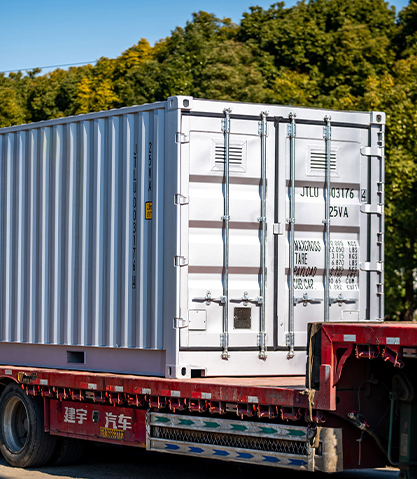
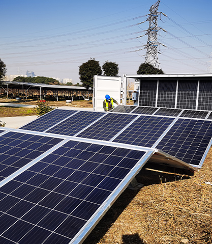
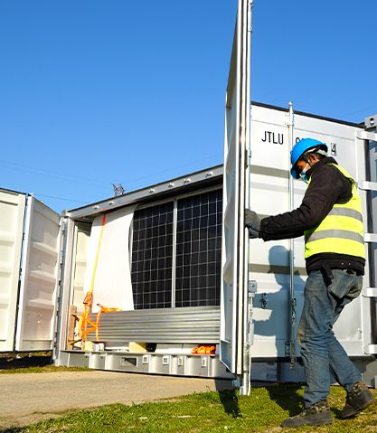
A tender document we reviewed last year asked for “one 60 kW power converter” to keep a workshop running after sunset. The load list was all lighting, bench tools and two small compressors — pure AC loads fed from a battery bank charged by solar. What the project actually needed was an inverter, and shipping a converter would have left the site with a very expensive battery charger and no usable power after dark.
That single line item is where a lot of budgets go sideways, because the two words are used interchangeably in casual conversation and never interchangeably in electrical engineering.
The short answer: an inverter turns DC from a battery or solar array into AC for equipment. A converter turns AC from the grid or a generator into DC to charge batteries, or shifts one DC voltage to another. If energy is leaving the battery to run loads, you are looking at an inverter. If energy is flowing back in, it is a converter. Hybrid units do both directions, which is why catalog labels stopped matching reality years ago.
Get the direction wrong and the symptoms appear weeks later: batteries that never quite reach full charge, motors that trip the unit on start-up, or a generator that runs all night because nothing is putting energy back into the bank.
Content
What Each Device Actually Does With the Electrons
Both are switching power electronics built around the same silicon. The difference is the direction of the energy path and the control logic that comes with it. This is also where you can see the whole chain explained for a real solar container: how a solar power container converts sunlight into usable electricity.
Inverter: DC in, AC out
An inverter draws from a DC bus, typically 48 V, 400 V or 800 V, and synthesises a 50 or 60 Hz sine wave through H-bridge switching at roughly 16 to 20 kHz, then filters it down to a total harmonic distortion under 3% on a decent pure sine unit. Sizing is driven by the AC load profile: the continuous rating must cover everything running at once, and the surge rating must absorb motor inrush, which is commonly three to five times nameplate for one to three seconds. Full-load efficiency usually sits between 93% and 96%, but drops noticeably below 20% load.
 EPL3000-10KTL Single-Phase Hybrid Inverter SeriesWall-mounted 3–10 kW hybrid inverter with battery compatibility, dual MPPT, up to 97.8% efficiency and remote monitoring options for residential and small commercial systems.View Product →
Converter: AC in, DC out, or DC in, DC out
A converter is a rectifier plus a DC-DC stage. Grid or generator AC is rectified into a DC bus for charging, with a defined charge profile: bulk, absorption and float for lead-acid, or constant current then constant voltage for lithium. The other common family never touches AC at all — an MPPT stage taking a 600 V PV string down to a 48 V bus, or a buck stage dropping 48 V to 12 V for control equipment. Charge converters are rated in amps, not kilowatts, because current is what sets charging time.
Pick an inverter when the load needs AC, the source is a battery or PV array, and the system must keep running when the grid drops.
Pick a converter when energy must go back into storage, a DC bus needs a different voltage, or the site runs mostly on generator and grid power.
Pick a hybrid unit when the site needs both directions and cabinet space, cabling and commissioning time are the binding constraints.
Side-by-Side Comparison for Specification Writing
The table below is the version we hand to procurement teams, because it settles most arguments before they reach a purchase order.
The Efficiency Numbers Datasheets Bury
Peak efficiency printed on the front page is measured at one specific load. In a hybrid system, every conversion step multiplies into round-trip losses, so a DC-AC-DC path through two mediocre devices can lose 15% of your generated energy before it ever reaches a load.
MPPT DC-DC
96%
Sine inverter
94%
AC-DC charger
88%
Modified sine
82%
Two other numbers rarely make it onto the marketing sheet: no-load draw, which sits between 10 W and 50 W on many inverters and quietly flattens a battery over a long weekend, and derating above 40 degrees Celsius, where most units lose 1.5% to 2.5% of rated output per additional degree.
Where the Two Devices Sit in Real Projects
- Off-grid and mobile solar containers: 38%
- Hybrid residential and light commercial: 27%
- Port shore power and marine: 18%
- Industrial and mining backup: 17%
The split above reflects the project mix we see across container-based systems, and it explains a pattern worth noting: the more a site depends on shore power or a generator, the more of the budget belongs to converters, while fully islanded sites spend it on inverters and storage. That is also why self-provided power supply projects rarely specify one device without the other. Port and shore applications are a good illustration, where a three-phase grid-tied unit handles the AC interface while a charger path looks after the battery.
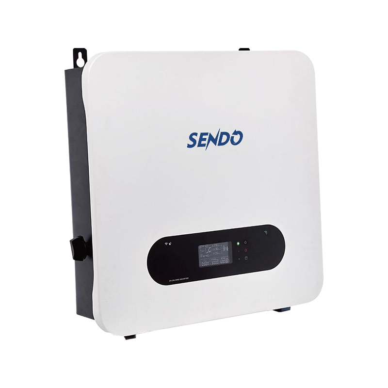 TP4-10KTL and TP10-25KTL Three-Phase On-Grid InvertersThree-phase grid-tied inverter range from 4 to 25 kW with dual MPPT, up to 98.7% efficiency, IP65 protection and remote monitoring for commercial solar installations.View Product →
A Five-Step Sizing Workflow
- List the loads in kW, with duty cycles. Separate resistive loads from inductive ones and note which start simultaneously, because coincidence factor decides the real continuous rating.
- Add surge headroom. Three times running load for compressor-driven equipment and five times for deep-well pumps is a safe planning figure; check the inverter datasheet surge duration, often only one to three seconds.
- Size the converter against battery chemistry. Roughly 10% to 20% of capacity in amps for flooded lead-acid, and 0.2C to 0.5C for lithium, unless the manufacturer states otherwise.
- Check the transfer path. Decide whether the system needs automatic changeover between grid, generator and inverter, and confirm transfer time against the loads that cannot tolerate a gap.
- Verify the AC interface. Confirm voltage window, frequency range, anti-islanding settings and neutral bonding before the unit leaves the factory, not after it arrives on site.
One procurement habit pays for itself: ask for the efficiency curve, not the peak number, and ask for the derating table at 45 degrees Celsius. Suppliers who can produce both usually have the test bench to back up the rest of the datasheet.
Maintenance and Compliance Details That Bite Later
- Bond neutral to earth in exactly one place. Two bonds in a system with an inverter and a converter create circulating currents and nuisance trips.
- Torque DC terminals to the manufacturer's figure at commissioning and again after the first thermal cycle; loose lugs are the most common cause of premature inverter failure in container installations.
- Keep the air path clear. A container that gains 10 degrees inside from stacked equipment can lose a fifth of its usable output on a hot afternoon.
- Record firmware versions at handover. Grid-code settings change, and a unit that was compliant at delivery may need an update to stay compliant two years later.
- For containerised storage, plan the service access before the unit is placed; battery modules that need lifting clearance are frequently boxed in by site logistics.
In larger systems the two functions end up inside the same enclosure anyway, which is why integrated ESS containers are specified as a single asset with one warranty boundary.
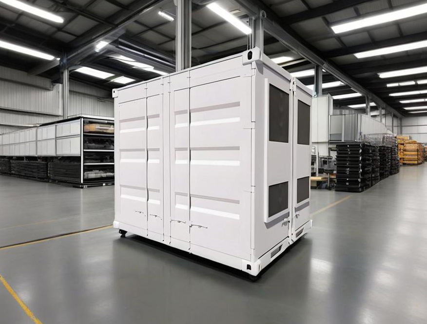 Containerized Battery Energy Storage SystemsContainerized ESS options from 1 MWh to 5.9 MWh for industrial and commercial peak shaving, backup power and grid support, with modular configuration and monitoring.View Product →
The practical takeaway is simple. Decide which way the energy flows at each point in your system, size the device for that direction, and treat the labels on the catalogue page as a description of hardware, not a substitute for a single-line diagram.
