 English
 中文简体
中文简体 عربى
عربى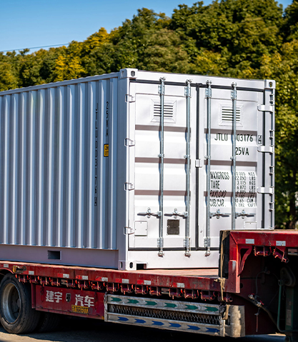
Content
- 1 What Are Solar Power Containers and Battery ESS Containers?
- 2 Internal Components of a Solar Power Container
- 3 Internal Architecture of a Battery ESS Container
- 4 Key Specifications to Compare When Selecting Containerized Energy Systems
- 5 Applications and Deployment Scenarios for Solar Power and Battery ESS Containers
- 6 Site Preparation and Installation Requirements
- 7 Maintenance Requirements and Expected Service Life
- 8 Cost Considerations and Total Cost of Ownership
What Are Solar Power Containers and Battery ESS Containers?
Solar power containers and battery energy storage system (ESS) containers are self-contained, modular energy infrastructure units built within standard ISO shipping container frames — typically 10-foot, 20-foot, or 40-foot configurations — that house all the electrical, mechanical, and thermal management components needed to generate, store, and distribute electricity at scale. A solar power container integrates photovoltaic (PV) inverters, power conversion systems (PCS), monitoring equipment, and the associated electrical switchgear into a weatherproof, transportable enclosure that can be deployed rapidly at virtually any location worldwide without requiring permanent civil infrastructure. A battery ESS container — sometimes called a BESS container — houses lithium-ion, lithium iron phosphate (LFP), or other battery chemistries alongside the battery management system (BMS), thermal management hardware, fire suppression systems, and grid interconnection equipment needed to store large quantities of electrical energy and release it on demand.
These two container types are frequently deployed together as an integrated solar-plus-storage system: the solar power container manages PV array input and grid synchronization while the battery ESS container handles energy buffering, peak shaving, frequency regulation, and backup power functions. The combination creates a complete, relocatable power plant that can serve remote mining operations, island grids, disaster relief efforts, military forward operating bases, industrial microgrids, and utility-scale renewable energy projects with equal effectiveness. The containerized format dramatically reduces installation time compared to conventional stick-built energy infrastructure — a project that might take 12–18 months to construct from scratch can often be commissioned using containerized equipment in 3–6 months, with significant reductions in civil engineering cost and site disruption.
Internal Components of a Solar Power Container
Understanding what is actually housed inside a solar power container is essential for anyone specifying, procuring, or maintaining one of these systems. The internal configuration varies between manufacturers and applications, but the core functional components are consistent across most commercial and utility-scale products. The container is not simply a weatherproof box — it is a precision-engineered electrical room that must satisfy stringent safety, cooling, and operational accessibility requirements within a highly constrained physical envelope.
PV Inverters and Power Conversion Systems
The central electrical components of a solar power container are the string or central inverters that convert the DC power output from connected PV arrays into AC power at grid frequency and voltage. Modern utility-scale solar power containers use high-efficiency three-phase inverters rated at 100 kW to 3,500 kW per unit, with multiple inverters operating in parallel within a single container to achieve total container power ratings of 500 kW to 5 MW or more. The inverters incorporate maximum power point tracking (MPPT) algorithms that continuously adjust the operating point of the connected PV strings to extract the maximum available power under varying irradiance and temperature conditions. In solar-plus-storage configurations, the inverter is replaced or supplemented by a bidirectional power conversion system (PCS) capable of operating in both rectifier mode (converting AC grid power to DC to charge the battery) and inverter mode (converting battery DC to AC for grid export or local load supply).
Medium Voltage Transformers and Switchgear
Most utility-scale solar power containers include a step-up transformer that raises the inverter output voltage — typically 400V to 800V AC — to medium voltage (6 kV to 35 kV) suitable for transmission over the distances commonly encountered on large solar farms and for interconnection with medium-voltage distribution networks. The transformer may be housed within the container itself or in a separate adjacent transformer enclosure. Low-voltage and medium-voltage switchgear — including molded case circuit breakers, vacuum contactors, surge protection devices, and energy metering equipment — is mounted in integrated switchboards within the container, providing protection and isolation for all electrical circuits. AC and DC surge protection is a critical safety component, preventing voltage spikes from lightning strikes or grid switching events from damaging the sensitive inverter electronics.
Monitoring, Control, and Communication Systems
A solar power container's monitoring and control system — often referred to as the SCADA (Supervisory Control and Data Acquisition) interface or energy management system (EMS) — collects real-time data from all electrical components, environmental sensors, and communication interfaces within the container and transmits this data to remote monitoring platforms via 4G/LTE, fiber optic, or satellite communication links. The EMS monitors parameters including DC string currents and voltages, inverter power output, grid voltage and frequency, container internal temperature, cooling system status, and grid power quality metrics. In solar-plus-storage systems, the EMS coordinates the operation of both the solar power container and the battery ESS container, implementing dispatch strategies that optimize self-consumption, maximize revenue from grid services, or ensure uninterruptible power supply to critical loads according to the operator's programmed priorities.
Internal Architecture of a Battery ESS Container
The battery ESS container is a more complex and safety-critical assembly than the solar power container, because it houses large quantities of electrochemical energy storage — a 40-foot ESS container may contain 2 MWh to 5 MWh of stored energy, equivalent to the energy content of hundreds of kilograms of conventional fuel — in a form that must be managed with exceptional precision to prevent thermal events, capacity degradation, and safety incidents. The internal architecture of a battery ESS container reflects this complexity in the number and sophistication of its integrated systems.
Battery Modules and Rack Configuration
The energy storage core of a battery ESS container consists of battery modules — assemblies of individual lithium cells arranged in series-parallel configurations to produce the required voltage and capacity — mounted in vertical racks that run the length of the container interior. Lithium iron phosphate (LFP) chemistry has become the dominant technology for containerized ESS applications due to its superior thermal stability (LFP cells do not undergo the thermal runaway reactions that have caused fires in other lithium chemistries), long cycle life (3,000–6,000 full cycles to 80% of original capacity at typical operating conditions), and competitive cost at scale. A standard 40-foot battery ESS container typically houses 8 to 20 battery racks, each rack containing 8 to 16 battery modules, with individual module capacities of 50 Ah to 280 Ah at nominal voltages of 48V to 100V. The rack voltage and capacity configuration is determined by the system's power conversion architecture and the target energy and power ratings of the complete ESS container.
Battery Management System (BMS)
The battery management system is the electronic intelligence layer that monitors every individual cell or group of cells within the ESS container and controls the charging and discharging process to maintain safe operating conditions and maximize battery longevity. A multi-level BMS architecture is standard in utility-scale ESS containers: cell-level or module-level BMS monitors individual cell voltages (typically with 1–5 mV accuracy), temperatures, and internal resistance; a rack-level BMS aggregates module data and manages the rack's contactors and balancing systems; and a system-level BMS integrates data from all racks and communicates with the EMS to implement the overall dispatch strategy while enforcing safety limits. Active or passive cell balancing — a process that redistributes charge between cells of different state of charge (SoC) to maintain uniform capacity utilization across the battery bank — is managed by the BMS and has a direct impact on long-term battery capacity retention and cycle life.
Thermal Management System
Battery cell performance and longevity are highly sensitive to operating temperature — LFP cells operate optimally in the range of 20°C to 35°C, and temperatures outside this range cause accelerated capacity degradation, increased internal resistance, and in extreme cases safety risks. The thermal management system of a battery ESS container maintains cell temperatures within the optimal range under all operating and ambient conditions, from arctic deployments at -40°C to desert locations where ambient temperatures exceed 50°C. Liquid cooling is the predominant thermal management approach for utility-scale ESS containers: a coolant circuit (typically a water-glycol mixture) flows through cold plates in direct thermal contact with the battery modules, extracting heat during charging and discharging and transferring it to an external heat exchanger or dry cooler unit. Heating elements integrated into the cooling circuit provide warmth during cold-weather operation to bring battery cells to minimum operating temperature before charge or discharge operations commence, preventing lithium plating on the anode that causes permanent capacity loss at low temperatures.
Fire Detection and Suppression Systems
Fire safety systems in battery ESS containers must be designed for the specific hazard profile of lithium battery fires, which differ fundamentally from conventional electrical or fuel fires. Early warning gas detection systems monitor the container atmosphere for hydrogen fluoride, carbon monoxide, and hydrocarbon gases that are released during the early stages of thermal runaway — the exothermic chain reaction that can occur when a lithium cell is damaged, overcharged, or exposed to extreme temperatures. Detecting these gases before any visible smoke or heat event allows the EMS to isolate the affected battery rack and activate the suppression system while the event is still manageable. The suppression system itself typically uses aerosol-based fire suppression agents or heptafluoropropane (HFC-227ea) gas, which suppresses fire by chemical interruption rather than oxygen displacement, making it effective in confined spaces without risk to personnel who might be present. Automatic venting systems prevent pressure buildup from battery outgassing from creating an explosion risk within the container enclosure.
Key Specifications to Compare When Selecting Containerized Energy Systems
Evaluating solar power containers and battery ESS containers requires a systematic comparison of technical specifications that have direct implications for system performance, total cost of ownership, and suitability for the intended application. The following table summarizes the most important specifications to request from manufacturers during the procurement process.
| Specification | Solar Power Container | Battery ESS Container |
| Rated power output | 500 kW – 5 MW per unit | 250 kW – 3 MW per unit |
| Energy capacity | N/A (flow-through) | 500 kWh – 5 MWh per unit |
| Inverter efficiency | 98.0% – 99.0% peak | 95.0% – 98.5% round-trip |
| Battery chemistry | N/A | LFP, NMC, or LTO |
| Cycle life (to 80% capacity) | N/A | 3,000 – 8,000 cycles (LFP) |
| Operating temperature range | -25°C to +55°C | -30°C to +50°C (with HVAC) |
| Grid connection voltage | 400V LV or 6–35 kV MV | 400V LV or 6–35 kV MV |
| Protection rating | IP54 – IP65 | IP54 – IP55 |
| Standard certifications | IEC 62109, UL 1741, CE | IEC 62619, UL 9540, CE |
Applications and Deployment Scenarios for Solar Power and Battery ESS Containers
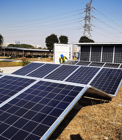
The versatility of containerized solar and battery storage systems has driven their adoption across a remarkably diverse range of applications. The common thread across all these deployments is the need for grid-quality electrical power at locations or under timelines where conventional infrastructure cannot be economically justified or rapidly delivered. Understanding the specific requirements of each deployment scenario helps in selecting the right container configuration and system architecture.
Remote and Off-Grid Power Supply
Remote mining operations, oil and gas exploration sites, agricultural facilities, telecommunications towers, and off-grid communities represent the largest and most established market for solar power containers and battery ESS containers. In these locations, the alternative to containerized solar-plus-storage is typically diesel generator sets — a technology with high fuel costs, significant logistical burden for fuel delivery, elevated greenhouse gas emissions, and high maintenance requirements in remote conditions. A solar power container integrated with a battery ESS container can typically displace 60–90% of diesel fuel consumption in a remote microgrid, with the remaining diesel backup capacity retained for periods of extended cloud cover or exceptionally high load demand. The payback period for the containerized solar-storage system relative to pure diesel generation depends on the diesel fuel cost (including delivery) and solar resource at the site, but commonly falls in the 3–7 year range for sites with high fuel costs, with system operating lives of 20+ years providing substantial long-term savings.
Utility-Scale Grid-Connected Energy Storage
Battery ESS containers are deployed in large numbers — sometimes hundreds of containers on a single site — to provide utility-scale grid services including frequency regulation, voltage support, peak shifting, and spinning reserve. These front-of-meter applications operate under contracts with electricity system operators that specify the power and energy capacity that the ESS must deliver, the response times required (typically seconds for frequency response), and the duration over which energy must be provided. The modular container format is particularly well suited to utility-scale ESS projects because it allows capacity to be scaled up in discrete increments as grid needs grow, and individual containers can be taken offline for maintenance without taking the entire installation out of service. Projects of 100 MW / 400 MWh capacity — requiring 80–200 battery ESS containers depending on individual container rating — have been commissioned in North America, Europe, Australia, and Asia to support the integration of increasing proportions of variable renewable energy into electricity grids.
Industrial and Commercial Demand Management
Factories, data centers, hospitals, universities, and large commercial facilities deploy battery ESS containers behind the electricity meter to reduce peak demand charges — a component of commercial electricity tariffs that penalizes facilities for their maximum power consumption during defined peak periods. By charging the ESS during off-peak hours when electricity is cheap and discharging it during peak tariff periods to reduce grid import, commercial and industrial users can substantially reduce electricity costs without reducing their operational capacity. Solar power containers paired with battery ESS containers in commercial microgrids add a renewable generation component to this strategy, allowing facilities to self-consume solar energy directly during daylight hours and store surplus generation for evening consumption or peak shaving use. Industries with on-site combined heat and power (CHP) generation increasingly use battery ESS containers to complement CHP output, smoothing the variable electricity export of the CHP unit and maximizing the value of on-site generation.
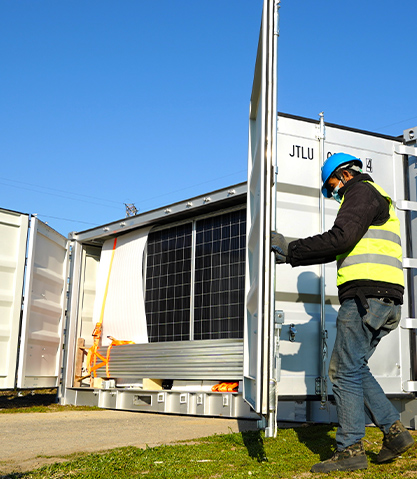
Emergency Power and Disaster Response
The rapid deployability of solar power containers and battery ESS containers makes them valuable assets for emergency power provision following natural disasters, infrastructure failures, or military and humanitarian operations in areas without functioning grid infrastructure. A containerized solar-plus-storage system can be transported to a site by standard flatbed truck, positioned using a forklift or crane, connected to load circuits, and generating power within hours of arrival — without requiring any permanent civil works or grid infrastructure. Governments, militaries, utilities, and humanitarian organizations maintain inventories of containerized energy systems for rapid deployment following hurricanes, earthquakes, floods, or other events that disable conventional grid infrastructure, providing power to hospitals, emergency coordination centers, water treatment facilities, and refugee accommodations while permanent grid restoration work proceeds.
Site Preparation and Installation Requirements
While containerized solar and battery storage systems are marketed as plug-and-play solutions requiring minimal site preparation compared to conventional energy infrastructure, a realistic assessment of installation requirements is essential for project planning and budgeting. Underestimating site preparation needs is one of the most common causes of project delays and cost overruns in containerized energy projects, particularly in remote locations where civil works are difficult and expensive.
- Foundation and leveling: Battery ESS containers must be installed on a level, load-bearing surface capable of supporting the combined weight of the container and its internal components — a fully loaded 40-foot battery ESS container can weigh 30,000–45,000 kg. Concrete pad foundations are standard for permanent installations; compacted gravel pads can be used for temporary or semi-permanent deployments where concrete is impractical. The foundation must be level to within 1–2° to ensure proper operation of cooling systems and to prevent mechanical stress on internal battery rack structures.
- Electrical interconnection infrastructure: Both solar power containers and battery ESS containers require high-current cable connections from the container terminals to the PV array DC combiner boxes, AC grid interconnection point, and load distribution panels. These cable routes — often hundreds of meters long in utility-scale installations — require trenching, conduit installation, and appropriate cable sizing for the fault current levels involved. Medium-voltage grid connections additionally require padmount or substation-type transformers, protection relays, and metering equipment that must be coordinated with the network operator's requirements.
- Cooling system external connections: Battery ESS containers with liquid cooling systems require external cooling infrastructure — typically air-cooled dry coolers or cooling towers — connected to the container's internal coolant circuit via insulated piping. The cooling system must be sized for the peak heat rejection requirement of the ESS under maximum charge or discharge conditions at the highest anticipated ambient temperature, which requires careful thermodynamic analysis at the design stage.
- Fire safety infrastructure: Local fire codes and insurance requirements typically mandate external fire detection systems, access roads suitable for fire apparatus, fire hydrant connections or water tanks for firefighting, and safety exclusion zones around battery ESS containers. Compliance with IEC 62933-5-2 (safety requirements for grid-connected energy storage systems) and local building and fire codes must be confirmed during the design phase.
- Communication and data infrastructure: Remote monitoring and control of solar power containers and battery ESS containers requires reliable communication links — fiber optic, cellular, or satellite — between the container EMS/SCADA system and the operator's remote monitoring platform. In utility-scale applications, cybersecurity requirements for grid-connected energy assets must also be addressed, including network segmentation, access control, and encrypted communication protocols.
Maintenance Requirements and Expected Service Life
Solar power containers and battery ESS containers are engineered for long operational lives — solar inverter components are typically rated for 20+ years of operation, and LFP battery cells can sustain 3,000–6,000 full charge-discharge cycles while retaining 80% of their original capacity, which at one cycle per day translates to 8–16 years of calendar service life. However, achieving these design lifetimes requires a structured preventive maintenance program and prompt response to condition monitoring alerts from the EMS and BMS systems.
Routine Preventive Maintenance Tasks
- Monthly inspections: Visual inspection of container exterior for physical damage, corrosion, or water ingress; verification of cooling system fluid levels and external heat exchanger cleanliness; review of EMS alarm logs for unacknowledged faults or performance anomalies; confirmation of fire detection system status indicators.
- Quarterly maintenance: Inspection and cleaning of air filters in HVAC and cooling systems; thermal imaging of electrical connections to identify developing hot spots before they cause equipment damage; verification of ground fault detection system operation; calibration check of voltage and current measurement systems against reference standards.
- Annual maintenance: Comprehensive electrical torque check of all bolted connections in switchgear, busbars, and cable terminations; replacement of cooling system fluid and filter elements; functional testing of fire suppression system (without discharging suppression agent); battery capacity test to measure actual available capacity against nameplate rating and track capacity degradation trend over the system's life; software updates to BMS, EMS, and inverter firmware.
- Long-term component replacements: Inverter DC capacitors and cooling fans typically require replacement at 10–12 year intervals; battery modules may require replacement at end of useful life (80% capacity retention threshold) or can be retained in second-life applications at reduced power ratings; fire suppression agent cylinders require hydrostatic testing and recharging at manufacturer-specified intervals (typically 5–10 years).
Cost Considerations and Total Cost of Ownership
The economics of solar power containers and battery ESS containers have improved dramatically over the past decade as manufacturing scale has increased, battery cell costs have fallen, and installation experience has streamlined deployment processes. Understanding the full cost structure — including capital expenditure, installation costs, operating expenses, and end-of-life considerations — is essential for accurate financial modeling and investment decision-making.
- Solar power container capital cost: Utility-scale solar power containers with integrated MV transformer and switchgear are typically priced in the range of $80,000–$200,000 USD per MW of AC power rating, depending on specification, brand, and order volume. This cost has decreased by approximately 70–80% over the past decade, driven by inverter cost reductions and manufacturing optimization.
- Battery ESS container capital cost: LFP battery ESS containers are currently priced in the range of $150,000–$350,000 USD per MWh of usable energy capacity, with significant variation based on discharge duration rating, power-to-energy ratio, battery cycle life warranty, and included BMS and thermal management sophistication. Battery cell costs — the dominant cost component — have fallen below $100/kWh at the cell level for large procurement volumes, and continued reductions are forecast.
- Installation and commissioning costs: Civil works, electrical interconnection, and commissioning typically add 15–30% to the equipment capital cost for utility-scale projects in locations with reasonable logistics access, rising to 40–60% or more for remote or challenging sites where civil works are expensive and specialized contractor mobilization is required.
- Operating and maintenance costs: Annual O&M costs for containerized solar-storage systems are typically 1–2% of initial capital cost per year, covering routine maintenance labor, consumable replacements, remote monitoring service fees, and insurance. Performance-based O&M contracts that include availability guarantees from the equipment manufacturer or a specialist O&M provider can provide cost certainty and transfer performance risk to the service provider.
- End-of-life considerations: Battery modules at end of first life (80% capacity retention) retain significant residual value for second-life applications in less demanding stationary storage applications, partially offsetting replacement costs. Recycling programs for LFP batteries are developing rapidly, with manufacturers increasingly offering take-back schemes that recover lithium, iron phosphate, and structural materials for reuse in new battery production.
