

 en
en  English
 中文简体
中文简体 عربى
عربى
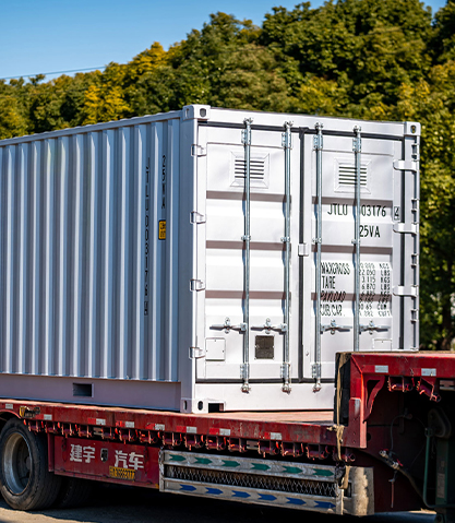
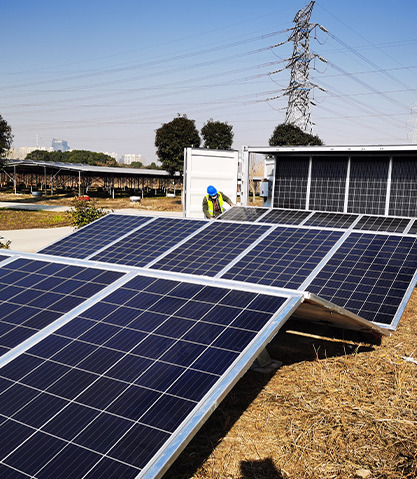
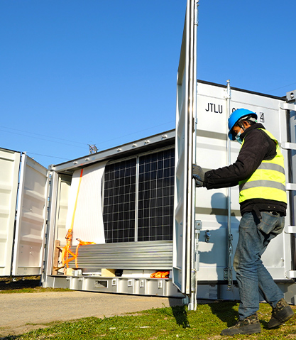
A solar cooling container operates on a deceptively simple principle: photovoltaic energy directly powers a high-efficiency vapor-compression or absorption refrigeration cycle, decoupling cold chain logistics from the electrical grid and diesel generators entirely. The system efficiency gains arise from eliminating the multiple energy conversion steps that plague conventional cold storage. In a typical grid-dependent cold room, fuel is burned at a power plant, converted to electricity, transmitted over long distances, stepped down through transformers, and finally fed to a compressor. Each conversion step loses energy as heat. A solar cooling container collapses this chain: photons strike the photovoltaic array, direct current flows to a variable-speed compressor, and the refrigeration cycle begins—all within the same physical footprint. The result is a 30 to 40% improvement in overall energy efficiency compared to grid-powered cold storage of equivalent capacity, and the elimination of operational fuel costs for the lifetime of the system.
The environmental and economic implications extend beyond pure cooling. When configured as a solar storage charging and battery swapping cabin, the same container platform provides fast charging services for electric vehicles while the energy storage system buffers the grid from the sudden load spikes that multiple simultaneous charging sessions would otherwise create. This dual functionality—cold storage and EV charging from a single solar-powered container—makes the system particularly valuable in urban and suburban locations where land is scarce and multiple infrastructure needs converge. Public parking lots, residential communities, and shopping malls can host a solar cooling container that preserves temperature-sensitive goods while simultaneously serving as a charging hub, all without requiring upgrades to the local electrical distribution infrastructure.
Content
Refrigeration Architecture and Thermal Efficiency
The cooling system within a solar cooling container is engineered for maximum coefficient of performance at part-load conditions, because solar irradiance varies continuously throughout the day. Unlike a conventional cold room compressor that cycles on and off at full power, the solar cooling container uses a variable-speed DC compressor that modulates its rotational speed in response to the available photovoltaic power. When solar irradiance is high at midday, the compressor runs at full speed, drawing 2 to 5 kW depending on the container size, and pulls the internal temperature well below the setpoint, effectively storing thermal inertia in the goods and the insulated structure. When a cloud passes or the sun angle decreases, the compressor slows proportionally rather than stopping entirely. This continuous operation eliminates the inrush current spikes and thermal cycling stresses that account for a significant portion of compressor wear and energy waste in conventional systems.
The thermal envelope of the container is the silent partner in achieving high system efficiency. Insulation specifications for a solar cooling container are substantially more demanding than for a standard refrigerated truck body because the container must maintain temperature stability with a variable energy input. The walls, floor, and ceiling are constructed with closed-cell polyurethane foam panels 80 to 120 mm thick, achieving an overall heat transfer coefficient of 0.15 to 0.22 W/m²·K. This level of insulation reduces the cooling load to the point where the photovoltaic array can maintain the target temperature even on days with only 3 to 4 peak sun hours. The table below compares the thermal performance of different insulation configurations and their impact on energy autonomy.
| Insulation Material | Panel Thickness | U-Value (W/m²·K) | Daily Cooling Load (kWh) at 35°C Ambient, 2°C Internal |
|---|---|---|---|
| Standard Polyurethane (PU) | 60 mm | 0.35 - 0.40 | 18 - 22 kWh |
| High-Density PU | 100 mm | 0.20 - 0.25 | 10 - 14 kWh |
| Vacuum Insulation Panels (VIP) | 40 mm VIP + 40 mm PU | 0.10 - 0.15 | 6 - 9 kWh |
| PU with Radiant Barrier | 80 mm + reflective foil | 0.18 - 0.22 | 9 - 13 kWh |
The choice of insulation directly determines the photovoltaic array size required and the battery capacity needed for overnight operation. A container with VIP insulation can maintain temperature through a full night on a battery bank of 10 to 15 kWh, whereas a container with standard 60 mm PU insulation would require 25 to 30 kWh of storage for the same autonomy. This difference cascades through the system cost, weight, and footprint, making the insulation specification one of the most consequential design decisions in the container's engineering.
Energy Supply Architecture and Photovoltaic Sizing
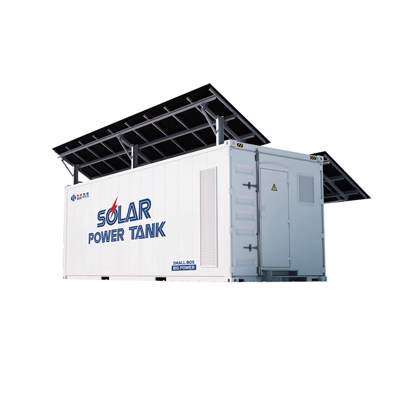
The photovoltaic array on a solar cooling container must be sized to cover both the cooling load and any auxiliary loads—lighting, controls, communication equipment, and in the case of a combined charging station, the EV charging demand. A standard 20-foot cooling container dedicated solely to refrigeration typically requires an installed PV capacity of 5 to 10 kWp, distributed across the roof and deployable folding arrays mounted on the container sides. The folding arrays, which extend outward when the container is stationary, can double or triple the available collection area compared to the roof alone, enabling a smaller container footprint to meet a larger energy demand.
When the container is configured as a solar storage charging and battery swapping cabin, the energy supply architecture becomes more complex. The photovoltaic array feeds a central DC bus that serves three parallel loads: the refrigeration compressor, the battery energy storage system, and the EV charging dispensers. An intelligent energy management system prioritizes these loads based on real-time conditions. The cooling load receives first priority to protect temperature-sensitive goods; any surplus generation charges the battery bank; and when the batteries are at an adequate state of charge, power is made available for EV charging. During periods of high EV charging demand, the energy management system can supplement photovoltaic generation with stored battery energy, ensuring that multiple vehicles can charge simultaneously without exceeding the container's rated output capacity.
Grid Balancing and Peak Shaving in Charging Applications
The integration of energy storage within the solar cooling container transforms it from a passive electricity consumer into an active grid asset capable of peak shaving and load shifting. In a public parking lot or shopping mall application, the uncontrolled charging of multiple EVs during the late afternoon—when the solar resource is declining and the grid is already stressed by residential and commercial demand—would create a problematic load spike. The container's battery energy storage system absorbs this conflict. During the midday solar peak, when the cooling load is satisfied and the batteries are fully charged, surplus generation is stored. When EV charging demand surges in the late afternoon and evening, the intelligent control system discharges the batteries to meet the charging load, reducing the grid draw by 70 to 90% compared to an unmanaged charging installation.
This peak shaving capability translates directly into reduced operating costs. Commercial electricity tariffs in many regions include demand charges based on the highest 15-minute average power draw during a billing period. A single unmanaged 50 kW DC fast charger can trigger a demand charge that adds $500 to $1,500 per month to the site's electricity bill. The solar cooling container's battery buffer absorbs the charging spikes, keeping the site's peak demand below the threshold that triggers these punitive charges. For property communities and shopping malls where multiple stakeholders share electricity costs, this demand charge avoidance makes the difference between an EV charging installation that is a financial burden and one that generates net revenue from charging fees.
High-Efficiency Flexibility Across Application Scenarios
The flexibility of the solar cooling container derives from its modular, self-contained architecture that can be reconfigured for different use cases without redesigning the core systems. The same base platform—a 20-foot or 40-foot insulated container with photovoltaic roof array, battery bank, and intelligent controller—can be equipped with different internal fittings to serve as a pharmaceutical cold store, a food preservation unit, an EV charging hub, or a battery swapping station. The internal temperature setpoint is software-configurable across a range from -25°C to +25°C, allowing the container to transition from frozen goods storage to ambient-temperature battery charging operations if the application demand changes over time.
Public Parking Lot and Shopping Mall Deployment
In these high-traffic urban locations, the solar cooling container solves two problems simultaneously. It provides convenient cold storage for retail tenants who receive temperature-sensitive deliveries throughout the day—floral shops, grocery vendors, pharmaceutical pickup points—without requiring each tenant to install and maintain their own walk-in cooler. At the same time, the container's EV charging dispensers serve shoppers who can charge their vehicles while browsing, with the charging session duration of 30 to 60 minutes well-matched to the typical shopping visit. The combination of services increases the container's utilization rate and accelerates the return on investment compared to a standalone cold store or standalone charger.
Property Community and Residential Integration
For residential communities, the solar cooling container functions as a neighborhood-scale shared infrastructure asset. Residents who lack private garages for home EV charging can use the container's charging stations on a scheduled or on-demand basis. The cold storage compartment can serve as a secure, temperature-controlled delivery drop point for online grocery orders, eliminating the need for doorstep deliveries that require the recipient to be home. The container's energy storage system smooths the community's overall electricity demand profile, potentially qualifying the property management for lower bulk electricity rates. Because the system is self-contained and requires only a level surface for deployment, it can be installed in an existing parking lot corner without excavation, trenching, or building permits for permanent structures.
Environmental Impact and Lifecycle Carbon Reduction
The environmental benefit of a solar cooling container extends beyond the obvious elimination of diesel generator emissions. A lifecycle carbon analysis must account for the embodied carbon of the container structure, photovoltaic panels, and batteries, offset against the operational emissions avoided over the system's 20 to 25-year service life. A 20-foot solar cooling container with a 10 kWp PV array and 30 kWh battery bank will generate approximately 14,000 to 18,000 kWh per year in a mid-latitude location. Over 25 years, this totals 350 to 450 MWh of zero-carbon electricity. If this generation displaces grid electricity with a carbon intensity of 0.5 kg CO₂ per kWh, the container avoids 175 to 225 metric tons of CO₂ emissions. The manufacturing carbon footprint of the container, PV panels, and batteries is typically in the range of 15 to 25 metric tons of CO₂ equivalent, meaning the system achieves carbon payback within 2 to 4 years and operates as a net carbon sink for the remaining two decades of its life.
The end-of-life strategy further improves the environmental equation. The container structure is fabricated from Corten steel, which is fully recyclable through standard scrap metal channels. The photovoltaic panels are subject to manufacturer take-back programs that recover the aluminum frames, glass, and semiconductor materials. The lithium iron phosphate batteries contain no cobalt or nickel, simplifying recycling and reducing the toxicity risk at end of life. When the container is eventually decommissioned, over 90% of its mass can be recovered and recycled, closing the material loop and minimizing the landfill burden. This circular design approach, combined with the operational emission savings, makes the solar cooling container one of the most environmentally benign cold chain and charging infrastructure options available for both developed and developing markets.
